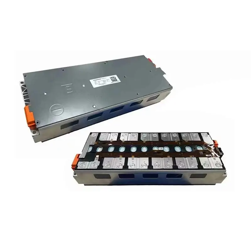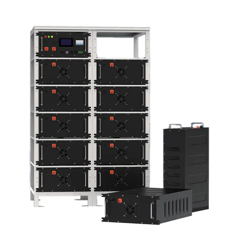
Prismatic lithium batteries generate expansion force during the charge and discharge processes. When these battery cells are assembled into a battery module, any expansion is partially absorbed by the battery cell casing itself, while the remaining force is transmitted to the battery module structure through casing deformation and internal gas pressure. Consequently, the generation and impact of this expansion force must be taken into account during the design and assembly of battery modules, ensuring that such forces are managed within an appropriate range.
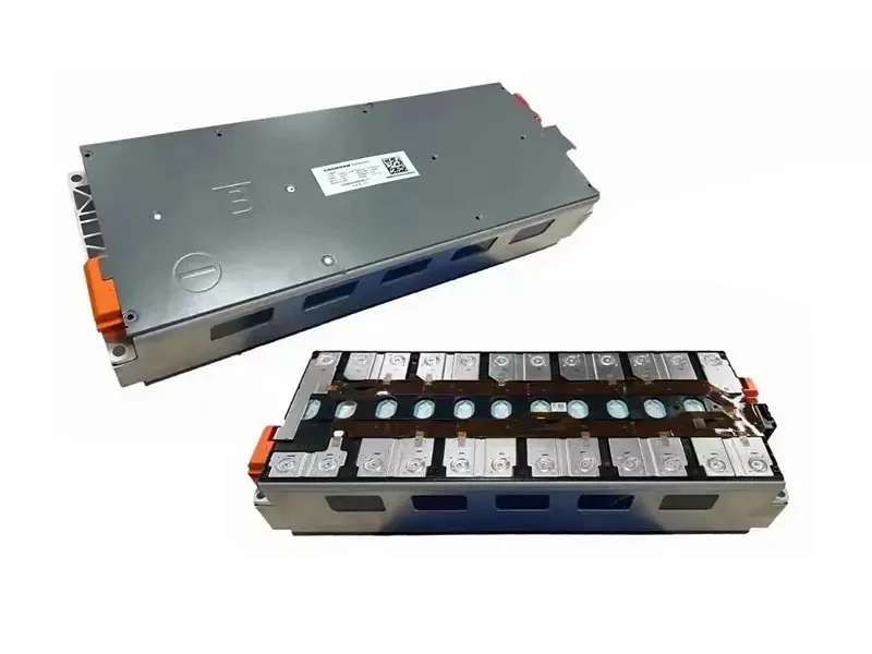
The Impact of Lithium Battery Expansion Force on Battery Module
Long-term Loading on Structural Component
The impact of expansion forces on a battery module is primarily manifested in the long-term loading experienced by its structural components. As battery cells undergo repeated expansion and contraction during cycling, the module’s end plates, straps, and fasteners are subjected to continuous, alternating loads. If the end plates lack sufficient rigidity or the straps possess inadequate creep resistance, the clamping force will gradually diminish, causing the cell stack to transition from a state of “uniform compression” to one of “localized loosening.” While such loosening does not immediately trigger a failure, it leads to uneven contact pressure between the cells, resulting in higher localized current density and accelerated capacity degradation; over the long term, this may even induce lithium plating.
Consistency
Furthermore, expansion force affects the uniformity of battery cell stacking. The casing of a prismatic battery cell does not experience uniform stress: the central area of its large faces has lower rigidity, while the edges and corners are more rigid; consequently, the casing tends to bulge toward the center during expansion. This means that even if the average clamping force applied by the module falls within an acceptable range, the actual surface pressure may be excessively high in the center and too low along the edges. Sustained high pressure in the central region increases the risks of separator deformation and lithium plating, while insufficient pressure at the edges can lead to poor contact or component displacement. If a battery module design considers only the average force, it may overlook localized risks stemming from this non-uniform distribution of surface pressure.
Gas Generation and Internal Pressure
Third, expansion force acts on the battery module indirectly through gas generation and internal pressure. In prismatic hard-cased cells, gas produced by the decomposition of the electrolyte first increases the internal pressure of the casing; this pressure exerts force on the casing walls, which is then transmitted externally as the casing bulges. If the casing possesses sufficient rigidity, internal pressure may build up before any significant change in external clamping force is observed; conversely, if the large surfaces of the casing lack sufficient rigidity, the bulging manifests more directly as an increase in the force experienced by the battery module. Therefore, the force perceived by the module is not strictly equivalent to the actual internal pressure within the battery cell; consequently, both the external clamping conditions and the tendency for the casing to bulge must be considered during the design process.
Low Temperature and High SOC
Fourth, low-temperature conditions and high states of charge (SOC) can render the effects of expansion force less apparent. At low temperatures, lithium ions accumulate on the surface of the negative electrode, increasing the propensity for lithium plating; the state of high stress is not automatically alleviated by the drop in temperature. When fully charged, the negative electrode reaches its maximum lithium-intercalation level, and expansion force typically peaks. In prismatic battery cells, the rigid casing suppresses visible deformation, meaning that internal local pressure could reach dangerous levels even while external readings remain within a normal range. If a module’s constraint system is evaluated solely based on room-temperature or high-temperature operating conditions, the risks associated with fast charging at low temperatures—or maintaining a high SOC at low temperatures—may be significantly underestimated.

How does the Expansion Force of a Lithium Battery Arise?
The expansion force of a prismatic lithium-ion battery cell originates primarily from three sources.
The first aspect concerns the volume change of electrode materials. During charging, lithium ions deintercalate from the cathode and intercalate into the anode; this causes the interlayer spacing of a graphite anode to expand, while a silicon-based anode undergoes even more drastic volume changes. Cathode materials also experience a degree of volume contraction or structural alteration during delithiation. The process is reversed during discharge. Since these volume changes recur with every cycle, long-term cycling can lead to the formation of cracks and the agglomeration of particles, rendering the volume changes no longer fully reversible. In a prismatic (rectangular) battery casing, this volume expansion is contained internally; as the electrode sheets expand, the large faces of the casing bulge outward. The displacement is greatest in the central region, while the edges and corners—owing to their higher structural rigidity—exhibit less displacement.
The second aspect involves the thickening of the solid electrolyte interphase (SEI) layer and gas generation. During the initial charge, an SEI layer forms on the surface of the negative electrode; as the battery cycles, this layer continuously grows and undergoes repair, leading to an increase in its thickness—a primary driver of irreversible thickness growth in the battery cell. Simultaneously, the decomposition of the electrolyte produces gas, which accumulates within the rigid casing and drives up internal pressure. SEI thickening contributes to a slow, monotonic increase in thickness, while gas generation leads to a rise in internal pressure. The impact of this pressure on external clamping force depends on the rigidity of the casing: the more rigid the casing, the more the gas pressure remains “locked” inside, resulting in less noticeable changes in external force readings. Conversely, the more flexible the large surfaces of the casing are, the more easily the swelling (bulging) is transmitted to the battery module.
A third aspect concerns how the cell casing structure redistributes internal stress. Following the stamping process, a prismatic casing exerts weaker constraint on the electrode assembly in the central region of its large faces, while exerting stronger constraint along the edges and at the rounded corners (R-corners). Furthermore, the mechanical behavior of the electrode assembly within the casing differs depending on whether it is of a wound or stacked configuration: a wound structure, when expanding radially, is constrained by the casing in a way that causes stress to concentrate toward the central core and the transition zones at the corners; in contrast, a stacked structure experiences relatively uniform stress in the thickness direction, allowing the positive and negative electrodes—along with the separator—to expand and contract in unison. Consequently, for prismatic cells with the same nominal capacity, the specific internal electrode assembly design dictates how expansion forces are transmitted to the module and where those forces become locally concentrated. Module design must therefore account for the specific internal structure of the electrode assembly; one cannot simply assume a uniform mechanical response based solely on the “prismatic” classification.
Temperature can amplify or alter the aforementioned processes. At high temperatures, reaction rates accelerate, leading to a more pronounced increase in expansion force; at low temperatures, the tendency for lithium plating intensifies, and states of high stress can persist. Rapid charging, meanwhile, simultaneously triggers increased gas generation, rising temperatures, and uneven lithium-ion concentration distribution, causing the expansion force to grow more rapidly and less uniformly.

How to Manage Expansion Forces in Module Design and Assembly?
To address the expansion force of prismatic battery cells, the core strategy is neither to “rigidly constrain the cells” nor to “simply leave ample space and ignore the issue.” Instead, it involves a two-tiered management approach—combining passive constraint from the housing with clamping force applied during module stacking—to ensure that the cells remain within an appropriate range of mechanical stress throughout their entire lifecycle.
1. Correctly Understand what the Battery Module Clamping Force Acts Upon.
In a prismatic hard-cased battery, the pressure on the electrode sheets is primarily determined by the passive constraint of the casing, whereas the end plates and straps of the battery module exert a clamping force on the stack of individual cells. The primary purpose of this clamping force is not to directly regulate the pressure on the electrode sheets, but rather to ensure uniform contact between the cells and to prevent displacement or loosening caused by vibration. Consequently, the goal in module design is to achieve an optimal range for the stack clamping force—more is not necessarily better. If the clamping force is too low, contact between cells becomes uneven, leading to localized high current density, accelerated capacity degradation, and, over time, potential lithium plating. Conversely, if the clamping force is too high, the separator may undergo compressive deformation, narrowing the ion transport channels; this likewise increases the risk of lithium plating and internal short circuits. The design objective is to maintain the clamping force within the middle of the target range, while providing sufficient margins on both sides to account for manufacturing variability and the increase in expansion force that occurs during cycling.
2. The End Plates and Straps must Ensure the Retention of Clamping Force.
End plates require sufficient rigidity to suppress long-term creep, while strapping must possess high tensile strength and resistance to creep. However, the concept of “reinforced end plates” only carries meaning when derived by working backward from a target clamping force window. More importantly, clamping force is not a static parameter set once and for all; factors such as SEI layer thickening and irreversible expansion during cycling cause the expansion force to rise continuously. If the initial clamping force is set near the upper limit of the target window, it may eventually push the system into a range where the risk of lithium plating arises. Conversely, if the initial value is too low, it can lead to uneven contact, thereby accelerating degradation during the early stages. Structural design should therefore focus on the ability to maintain the clamping force throughout the entire product lifecycle, rather than merely on a single reading taken at the time of assembly.
3. Cushioning Materials and Reserved Gaps must be Matched to the Deformation Characteristics of the Housing.
The function of cushioning material is to accommodate the bulging displacement of the battery casing, smooth out fluctuations in clamping force, and provide a margin for irreversible thickness growth—rather than to “generate” a pre-tightening force on the electrode sheets. In a prismatic casing, displacement is greater in the center and smaller toward the edges; therefore, the compression of the cushioning pad should be tailored to match this distribution. If the thickness or stiffness of the pad is uniform across its surface, the central area may become fully compressed—losing its cushioning capacity—before the peripheral areas have had a chance to function effectively. The reserved gap must also be carefully determined: if it is too small, the cell will be subjected to excessive external pressure as it expands; if it is too large, it results in wasted space and may allow the cell to shift within the module. The dimensions of the gap, the selection of cushioning material, and the target clamping force should be determined iteratively as an integrated system.
4. The Compression Phase of Steel-strap Packaging must be Included in the Material Verification Process.
When using steel straps to secure prismatic battery modules, the modules must first be compressed to a size slightly smaller than their design dimensions to allow the steel straps to be positioned correctly. This means that, during assembly, the cushioning material is subjected to an instantaneous level of compression that exceeds the target clamping force. If the cushioning foam undergoes significant permanent deformation—due to over-compression or long-term sustained compression—the actual clamping force may drift outside the target range early in the operational cycle, even while the target values specified in the process documentation appear to remain within limits. Therefore, when evaluating cushioning materials, it is not sufficient to consider only the steady-state compression curve; one must also assess permanent deformation and recovery capability following a history of over-compression, ensuring that the clamping force returns to the target range once the steel straps are locked and the initial assembly pressure is released.
5. Focus on In-plane Stiffness Distribution
In a prismatic battery cell, the center is subject to weaker constraint, while the edges are more tightly constrained; furthermore, the winding process of the jelly roll tends to concentrate stress toward the central void and the transition zones near the corners. If an end plate is designed solely based on average load requirements, the central region may still experience localized overloading. For large-format prismatic cells, the in-plane stiffness distribution of the end plate must be carefully coordinated with the strategic placement of buffer pads to ensure that the actual surface pressure remains balanced—neither excessively high in the center nor too low at the edges. During the assembly process, the variability of the preload must also be strictly controlled; the actual surface pressure exerted on the cell stack should be verified through direct pressure measurement, rather than relying solely on indirect indicators such as bolt torque or steel-strap tension.
6.Simulations and Operating Condition Verifications must Account for the Coupled Response Between the Housing and the Cell Assembly.
Finite element analysis (FEA) of prismatic battery modules cannot rely solely on nominal material parameters for the battery cells. Instead, it must account for the spatial variation in stiffness resulting from the casing-stamping process, the expansion behavior of the internal electrode stack, and the preloading sequence. The primary challenge in such simulations lies in selecting the appropriate objects for calibration and accurately replicating the preloading history, rather than in the software operation itself. Regarding load-case verification—beyond standard-temperature cycling and high-temperature expansion—scenarios such as low-temperature fast charging and storage at low temperatures with a high state of charge (SOC) must also be included in the load spectrum. This is because a prismatic casing can “conceal” high internal stresses; the absence of visible external bulging does not necessarily mean that the internal pressure is within safe limits.
Summary
Managing the expansion force in prismatic lithium battery is, in essence, a two-stage constraint problem: the cell casing provides the primary, passive constraint, while the battery module assembly provides the secondary, stack-level clamping. Battery Module design must not treat the battery cell as a homogeneous body subject to uniform stress, nor should it rely solely on “clamping” or “leaving gaps” as isolated strategies. Instead, the approach requires understanding how expansion forces originate within the casing and how they are transmitted to the battery module through casing deformation and gas generation. During design and assembly, the stack-clamping force should be maintained within an optimal, moderate range. This involves ensuring that end plates and strapping mechanisms can effectively sustain clamping force, aligning cushioning materials and designated gaps with the deformation characteristics of the casing, accounting for the permanent material deformation of steel straps under excessive compression, addressing the distribution of in-plane stiffness and risks in the central region, and incorporating challenging operating scenarios—such as low-temperature fast charging—into the validation process. Only through this comprehensive approach can a proper balance be struck between safety, service life, and structural reliability.